
Trivia Records | Trivia zapisi
Trivia Records / Zapisi si online archiving, publishing facility for various formats - commonly known as multimedia or intermedia. A long-term project of Trivia Art Association.
free download
| Short Name: Cirkulino Description: arduino 8-step midi sequencer & controller shield Author: Borut Savski Homepage: http://www.ljudmila.org/~savskib/?p=154 Bill of materials 1 x 2,56 mm pins header ladder to connect to arduino 1 x HEF 4051 8-channel analog de/multiplexer 4 x resistors 10K - 22Kohms 3 x resistors 100 - 270 ohms 5 x potentiometer linear 10K to100Kohms 11 x pcb mount push-switches 8 x LEDs 3mm white or blue 1 x LED 3mm red 1 x LED 3mm yellow 1 x LED 3mm green 1 x small signal diode 1N4148 or 1N914 + Cirkulino board + arduino UNO (or Duemilanove, Diecimila) standard prototyping board The shield fits in hamburger manner - with he future option of "salami" in-between... The schematics is in the image file below named "Cirkulino schematics", the pcb is in "Cirkulino pcb" and the elements layout is in "Cirkulino layout". Current version is 3. Additionally there is a image file called "MidiInOut layout" - it is a simple midi in/thru and midi out board. If you just need standard midi out then you don\'t need it. This is how you connect it: http://arduino.cc/en/Tutorial/Midi We use this library: http://playground.arduino.cc/Main/MIDILibrary We also use interval interrupt library: http://playground.arduino.cc/Code/FrequencyTimer2 We try to use PROGMEM library (http://www.arduino.cc/en/Reference/PROGMEM) but we don't know yet how to... - we dropped this for now Arduino programming patch We try to use the standard arduino programming functions as much as possible. For rotary display we need higher pwm frequency. There is maybe a bit too much randomizing functions in the patch - this is due to my personal preoccupations. This can be eliminated with a setting in Cirkulino patch. The patch consists of three patches: - Cirkulino3_8.ino is the main with all definitions, the main program engine and all midi out stuff - displayPart.ino is holds interrupt routine and functions for sensing the switches and lighting the rotary leds - randomPart.ino holds all the random functions The board may be used to send notes on three midi channels - along with additional control changes - this is the sequencer mode. We can program separate sequencer patterns for three midi channels (1, 2 and 3). In sequencer mode the notes are generated randomly but with options to follow some scales. There are functions for forward, reverse and palindrome sequencing. The top MODE switch handles these changes. Consecutive pushes on MODE switch jump through the above three options. The default self-suficient sequencer operation also defines the potentiometer functions: - left bottom pot defines PITCH - left top pot defines (random) EVENTS (zero position: no random events) - the top middle pot is for CLOCK (or speed) - the top right pot is TONALITY (various scales) - the bottom right pot is for VELOCITY (volume) A configuration in patch disables this functions and lets you use the pots as additional control change controllers. Control changes are sent on midi channel 1. You can switch from sequencer to controller mode and back with a push on both MIDI CH 2 and MIDI CH 2 buttons (the two buttons just above the rotary switches). In controller mode Cirkulino functions as controller interface - to send control changes (corresponding to the five potentiometers: cc0, cc1, cc2, cc3, cc4). The rotary switches then function as note triggers on midi channel 1. Notes progress in C-major scale - starting from top switch (C1=note 36) to the eight switch (C2= note 48). Holding down the MIDI CH 2 switch transposes this an octave lower, and holding down the MIDI CH 3 switch transposes notes by octave higher. So: quite a lot of possibilities for triggering stuff. Control changes from the five pots are again sent on midi channel 1. To connect to some computer music software we need to convert serial data to midi. Hairless Serial-Midi converter is such a program. To route midi data between the software (in Windows) we use MidiYoke. We can have multiple instances of serial-midi converters - three were used without any problems. A classic midi output can be added easily but we have to change the baud rate to midi standard - but then we are away from standard serial baud rates. The patch is very "beta" but fully working and it should probably branch to specialized patches. The hardware is now almost determined, so the research is very much only in software. Below are zipped packages of the patch. The latest version is Cirkulino3_8 and solves a lot of things. Download .zip and extract it into your Arduinbo Sketchbook folder. The pcb layout is below ("cirkulino pcb"). It can be made with printing it on the foil and using photo-method or some other \"one of\" solution. The correct side of the circuit is as bottom copper - so that the version number is correctly printed on the copper side. The elements mounting pictures (green) are for older version. The correct version is "Cirkulino v.2 layout". However the board still allows for the narrow version - with pots on the top. Download these files 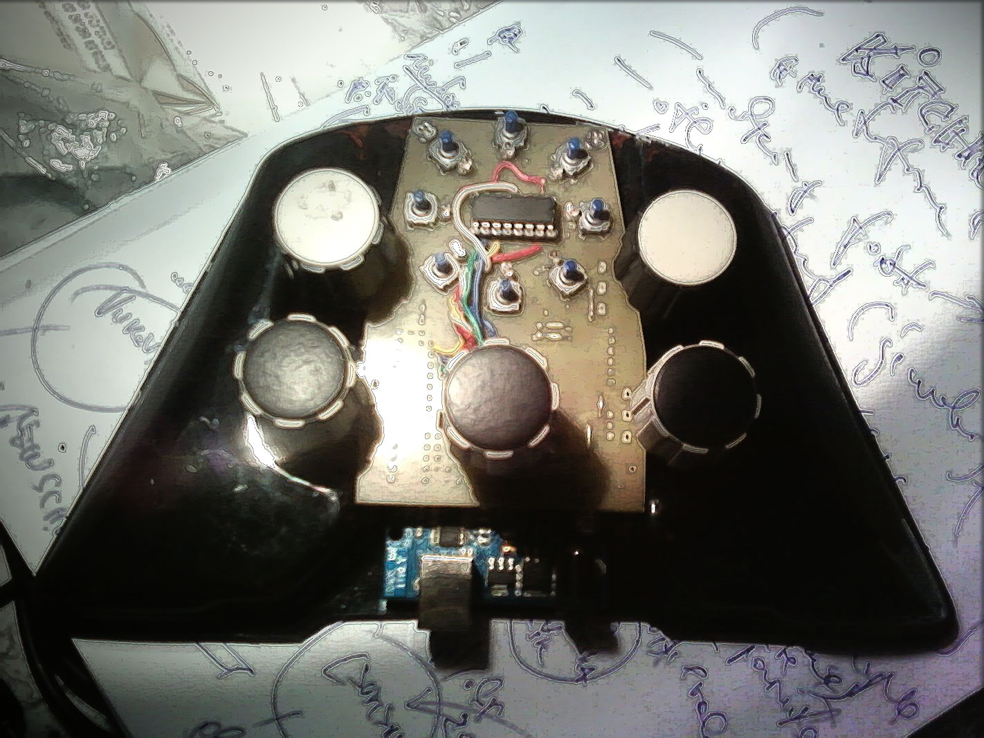   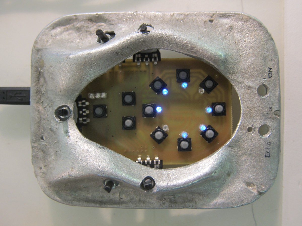 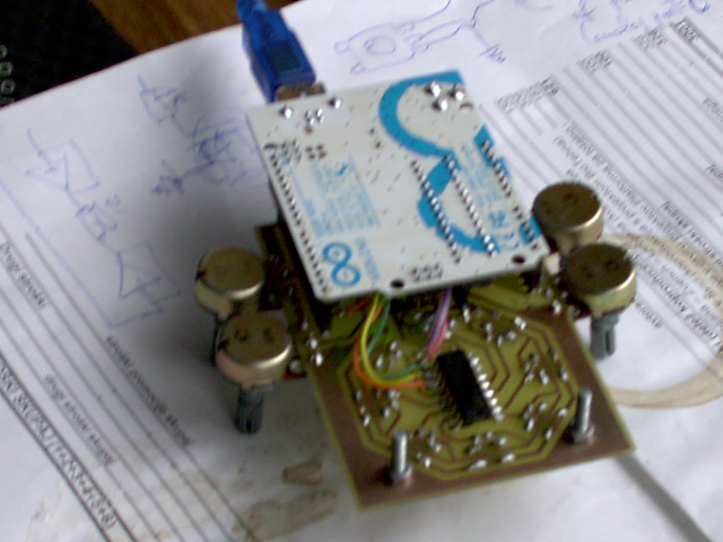 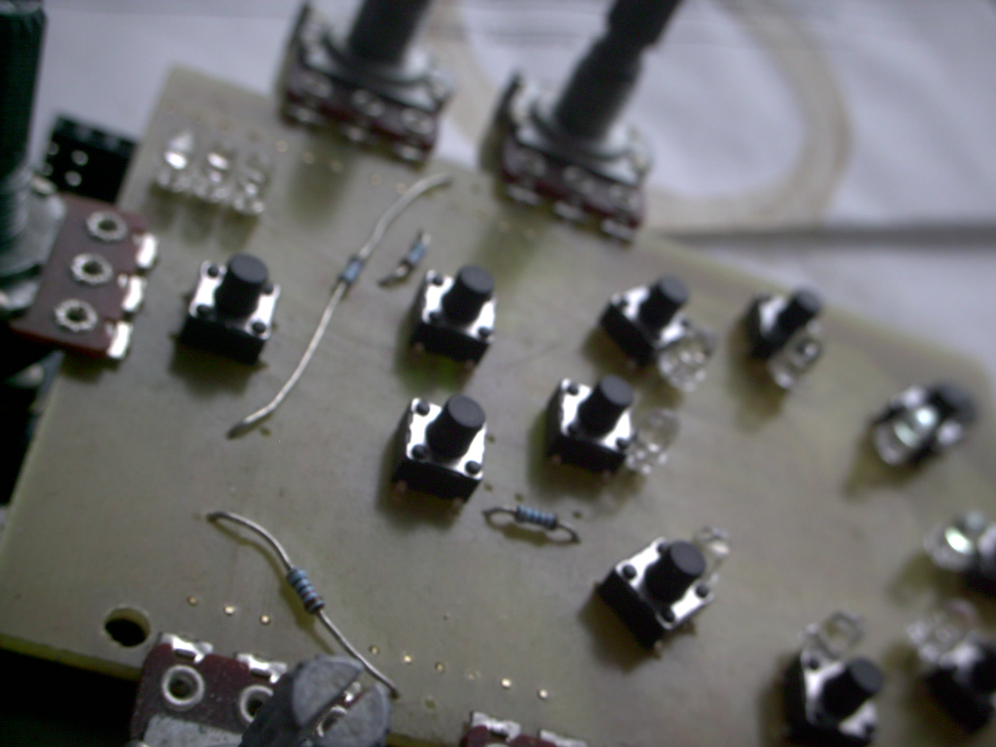 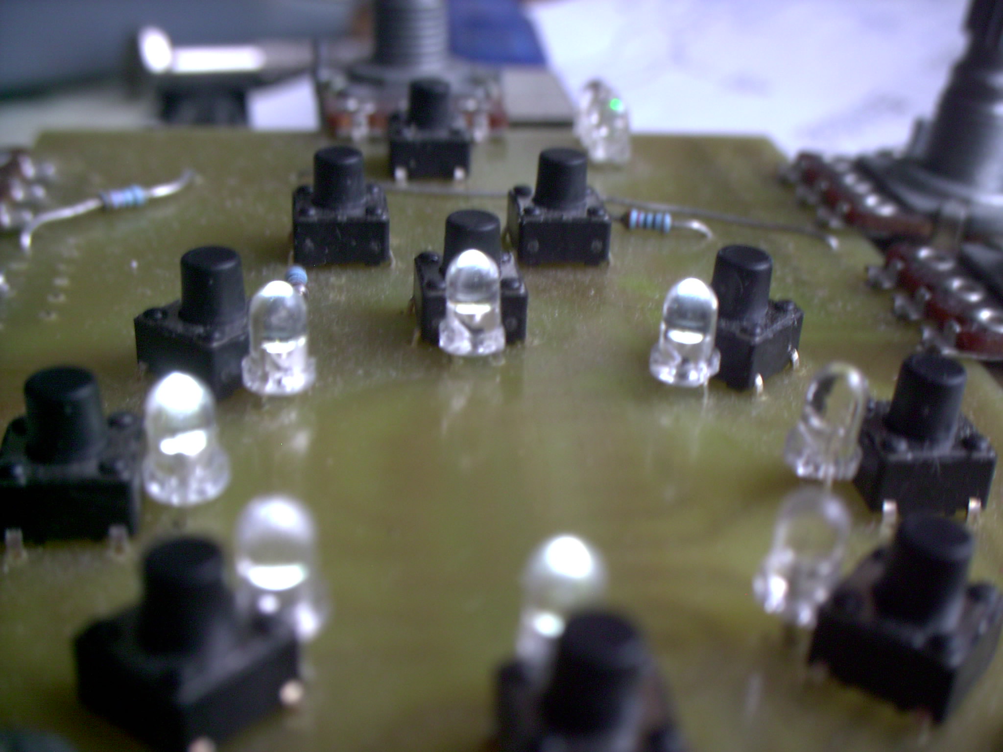 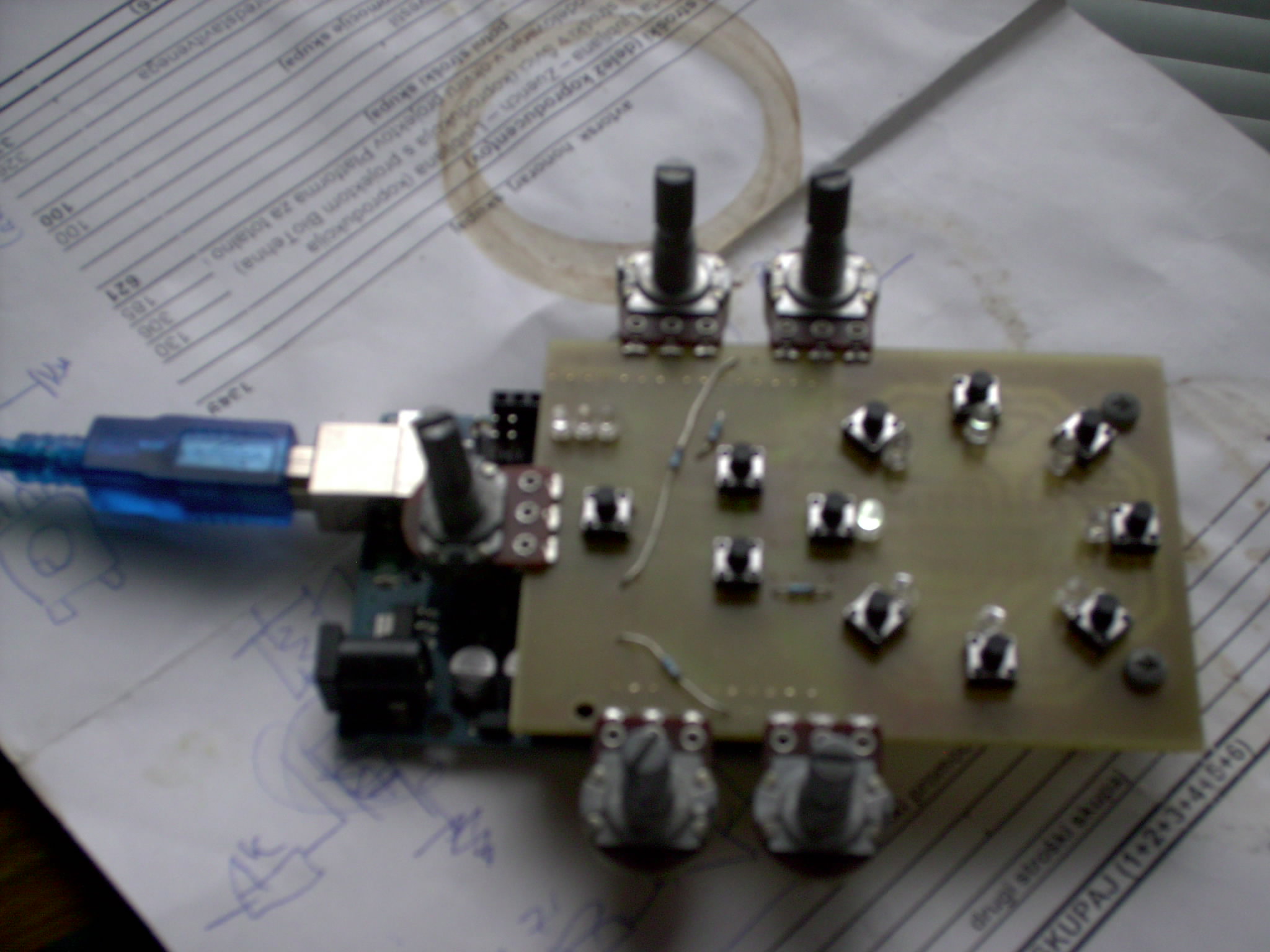   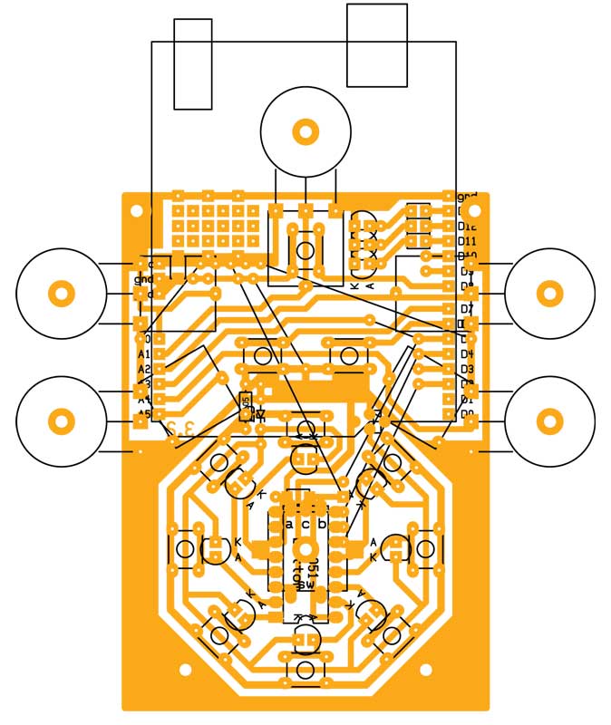 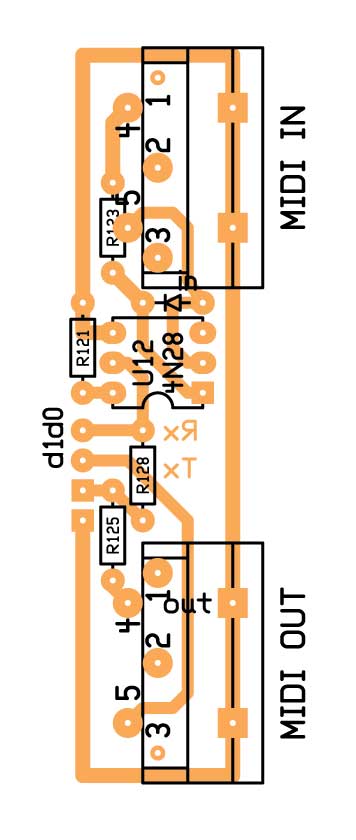 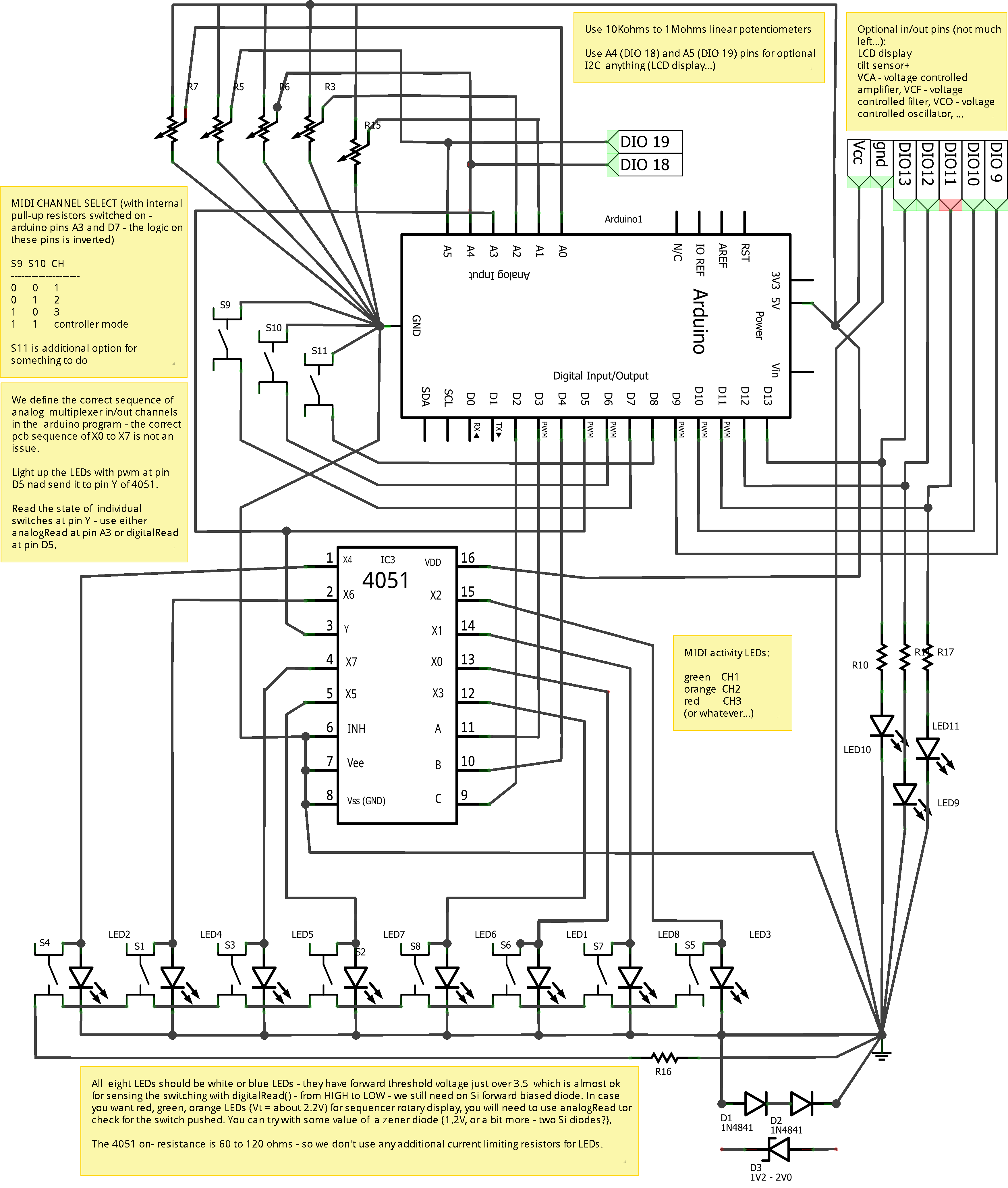 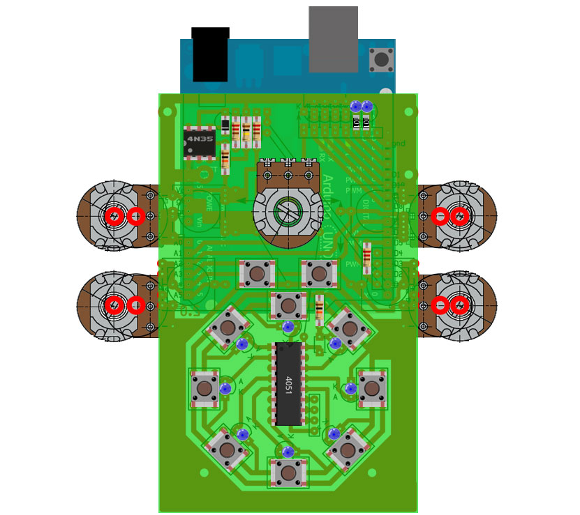 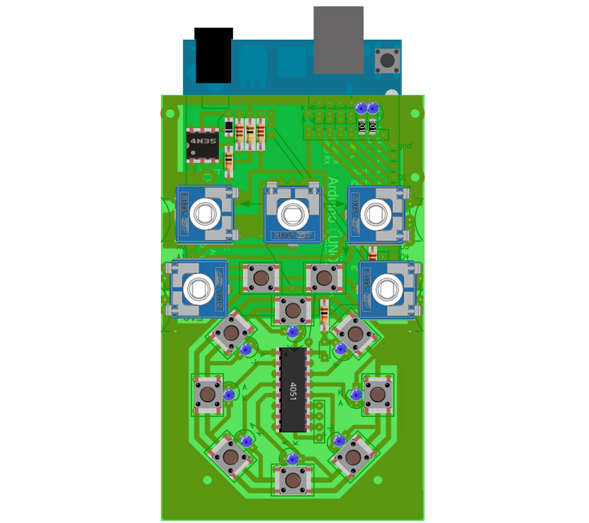  pdf HCF4051.pdfpdf MidiInOut pcbpdf Cirkulino v.3 layoutpdf Cirkulino v. 3 pcb pdf HCF4051.pdfpdf MidiInOut pcbpdf Cirkulino v.3 layoutpdf Cirkulino v. 3 pcb zip cirkulino_arduino_libraries.zipzip Cirkulino3_8.zip zip cirkulino_arduino_libraries.zipzip Cirkulino3_8.zipLinked items  Borut Savski - my name is Cirkulino and i work on arduino Borut Savski - my name is Cirkulino and i work on arduino |
Description Basic rule: the smallest amount of elements… - five potentiometers for manipulation of midi data (velocity, sustain, pitch,…, controllers), rhythms/ events - with some presets / including various random options that prove interesting (on the level of pitch, velocity, rhytmic event, tonality). - eight push switches, eight-channel analog multiplexer/demultiplexer CMOS chip 4051 (74HCF4051, CD4051) for activation/ deactivation of individual sequence steps and eight LED for visualisation of active steps - the 4051 has internal on-resistance of 50 to 150 Ohms, so we don\'t use any limiting resistors for eight LEDs - to sense/read the pushed switches we use a 10 Kohms resistor as the lower part of voltage divider – the upper part is the so-called pullup resistor in atmel microcontroler on arduino board - there is a silicon diode on the common cathode of rotary display LEDs - this is needed to increase the voltage drop on the combination of LED and diode to over the threshold defined for logic one (HIGH) - in order for the push on switches bring it to the logic zero (LOW). - two push switches are used to select different steps for two additional midi channels in sequencer mode or for some notes\' transposition in controller mode. - three LED and limiting resistors 100 to 220 ohms show midi channels activity (or a note on and note transposition in controller mode) - there is a (too large...) number of flying wires, sometimes flying resistors - because of single sided PCB.
HEF4051 is eight channel analog switch which receives binary encoded data on three pins to select one of eight channels. The chip is just opening and closing internal transistor switches to the common pin - it provides no power for the LEDs. Reading of switches and writing of LEDs are performed in interval interrupts in the following sequence: - every 4000 microseconds (or so) there is a call for interrupt routine where we check for the current states of all switches and also send current to rotary display LEDs - we select the current multiplexer channel to read or write (with three binary encoded pins from Arduino board we open/close/scan individuaslly the eight inputs/ outputs of 4051 multiplexer) - we first define LED not to glow – arduino pin 5 - then we redefine arduino pin 5 as input, activate the internal pull up 20 Kohmov - read pin 5 - if the selected switch is pushed (to ground) the voltage on pin 5 is just below the threshold of LOW, or it is above (0.6 * Vcc) – so the logic \"one\" (1, HIGH) - compare and remember the new value - next deactivate the pull-up resistor on pin 5 - redefine arduino pin 5 as output to prepare to write to LED - during each interrupt we increment by one the current sequence step - each time we check for the state of the current step - it can be 0 or 1 - we also show the circulation of steps. We do this with full brightness of the current step (override the previous) - so, the LED glows:
Main problem in this \"common pipeline\" for reading and writing is that the corresponding LED is always there - going to the ground. There is the necessary change on reading when the switch on the same channel is pressed, but different types of LEDs have different resistances/ threshold voltages (2.2 to 2.6 V for red, green, yellow - and 3.2 to 3.5 V for white and blue). At first I used analogRead() arduino function where the setting of threshold programatic, but the reading was at some steps too slow and the step "hanged". Using digitalRead() - as described above - limits the eight display LEDs to white or blue color. The threshold voltage is around 3.5V - for other colors it is around 2.5V and less. But in all cases we have to use some additional threshold thingy - a forward biased silicon diode adding 0.6V to the cathode side. For white and blue a small signal Si diode seems to be ok (1N914, 1N4148). In some cases a 1A rectifier diode did the trick and also b-e pn junction of bipolar Si transistor is ok. For other colors we would need around 1.5V added - three diodes in series - or a Zener-diode 1.8V. I tested it some time ago but it was at that time dissapointing. Solution: use medium to high brightness white LEDs for the rotary display! |

